
The FTTH Drop Patch Cord is a crucial component in fiber optic networks, serving as the final connection between the outdoor fiber distribution point and the user's indoor equipment. Selecting the right patch cord impacts not only the network’s performance but also its longevity and ease of maintenance. With numerous types and specifications available, understanding key factors and industry standards is essential for network planners, installers, and operators.
 Compliance with international standards ensures interoperability and safety. Important standards include IEC 61754, which defines connector interfaces ensuring mechanical and optical compatibility; ISO/IEC 11801, which outlines performance requirements for structured cabling systems including patch cords; and IEC 60794-1, specifying mechanical and environmental requirements for optical fiber cables, including strength and fire safety parameters. Verifying that patch cords meet these standards is essential to guarantee network quality and reliability, especially in large-scale or commercial deployments.
Essential Criteria for Selecting FTTH Drop Patch Cords
Choosing the best FTTH Drop Patch Cord requires evaluating several critical factors that directly influence signal integrity and installation flexibility.- Fiber Type and Bend Radius: Most modern FTTH drop cords use 657A2 bend-insensitive fiber, capable of handling bends with a minimum radius of 7.5 mm without exceeding 0.1 dB additional loss. Compared to traditional G.652D fiber, which requires a bend radius above 30 mm, G.657A2 fibers significantly reduce signal attenuation in tight indoor spaces like wall conduits or ceilings.
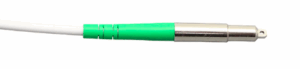
- Connector Type and Polishing: SC, LC, and FC connectors are common. The choice between Ultra Physical Contact (UPC)and Angled Physical Contact (APC) polishing impacts reflection and return loss. APC connectors offer return loss values of ≥60 dB, which is especially important in GPON systems to minimize upstream signal interference. UPC connectors are generally used where return loss requirements are less stringent.
- Cable Jacket Material: For indoor use, Low Smoke Zero Halogen (LSZH)jackets are preferred due to low toxic emission and smoke in case of fire, meeting IEC 61034 and IEC 60754 standards. In outdoor-exposed areas, cables with UV-resistant polyethylene (PE) jackets are recommended for longevity.
- Mechanical Strength and Durability: Reinforced aramid yarn (Kevlar) ensures tensile strength typically over 100 N, protecting the fiber from damage during installation and maintenance.
Common Applications and Length Considerations of FTTH Drop Patch Cords
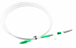
FTTH Drop Patch Cords are used primarily in three environments: residential homes and MDUs, commercial and office buildings, and temporary installations such as events or construction sites. Typical lengths vary from 5 to 30 meters depending on building size and fiber routing. The small diameter (2–4 mm) allows for flexible installation within narrow conduits and wall spaces, often concealed for aesthetic and safety reasons. In commercial buildings, patch cords provide short interconnects between fiber distribution panels and ONUs or switches in wiring closets, often with multiple cords requiring clear labeling and consistent performance. Temporary deployments benefit from pre-terminated FTTH Drop Patch Cords that can reduce installation time by as much as 60%, enabling technicians to complete connections within two minutes per drop and minimizing network downtime in fast-paced environments such as events and construction sites.Industry Standards and Certification to Look For in FTTH Drop Patch Cords
Compliance with international standards ensures interoperability and safety. Important standards include IEC 61754, which defines connector interfaces ensuring mechanical and optical compatibility; ISO/IEC 11801, which outlines performance requirements for structured cabling systems including patch cords; and IEC 60794-1, specifying mechanical and environmental requirements for optical fiber cables, including strength and fire safety parameters. Verifying that patch cords meet these standards is essential to guarantee network quality and reliability, especially in large-scale or commercial deployments.
Installation Best Practices to Maximize FTTH Drop Patch Cord Performance
Correct installation techniques are vital to preserve the FTTH Drop Patch Cord’s optical performance and extend its operational lifespan. Key guidelines include:- Maintain the minimum bend radius at all times to avoid micro-bending losses.
- Use dust caps until final connection to prevent connector contamination.
- Label cords clearly at both ends to facilitate future troubleshooting and maintenance.
- Perform post-installation tests using an Optical Power Meter (OPM) or Optical Time Domain Reflectometer (OTDR) to verify insertion loss is below 0.3 dB.