In fiber optics, testing of the transceivers plays a vital role in ensuring stable data transfer. Testing should be conducted before installation of the modules or when checking the connectivity of the network. An MTP Loopback can be used in such circumstances to test the operation of the transmitting and receiving channels. This is achieved by directing the optical signals through the transmitting channels back to the receiving channels.
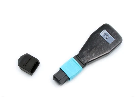
1. What Is an MTP Loopback?
Definition and Basic Structure of an MTP Loopback
An MTP Loopback is a passive fiber optic testing accessory that connects the transmit (TX) and receive (RX) channels of a compatible optical transceiver. It redirects outgoing optical signals back to the receiving ports of the same transceiver instead of sending them through an external fiber link. This results in a closed optical loop that is used to verify the transmitting and receiving capabilities of the transceiver. This method is mostly applied in data centers and fast fiber optic networks. The main components include MTP connectors and fiber connections that depend on the channel mapping requirements. Different types of connectors and different numbers of fibers are available.Components of MTP Loopback: MTP Connector, Fiber Optic Cables, and Internal Connections
The structure of an MTP Loopback is quite simple; nonetheless, all components are important for achieving proper compatibility and signal transmission.- MTP connector: Acts as an interface between numerous optical fibers. Common MTP connectors include 8-fiber, 12-fiber, and 24-fiber types.
- Internal fiber optic cables: Provide transmission of optical signals between TX and RX ports. The cables must match the transceiver.
- Internal connections: Transmit the signal from TX ports to respective RX ports in accordance with polarity.
- Connector housing: Protects internal fibers and makes the accessory easier to use.
2. How Does an MTP Loopback Work?
The operating principle of an MTP Loopback is based on redirecting optical signals from the TX channels to the corresponding RX channels. The process involves four stages, beginning with signal transmission and ending with transceiver detection.Optical Signal Transmission from the Transceiver
The test begins when an optical transceiver or connected testing system generates optical signals through its transmitting channels. These signals travel from the TX ports into the connected loopback accessory. The number of active channels depends on the transceiver interface. For example, a typical 40GBASE-SR4 or 100GBASE-SR4 interface uses four transmitting lanes and four receiving lanes, requiring eight optical fiber positions for the four-lane TX/RX arrangement. The chosen accessory needs to match the transceiver’s fiber type, wavelength, and channel. The multimode SR4 interface usually works at 850 nm, and other optical standards may work at other wavelengths.TX-to-RX Connection Through Internal Fiber Routing
After entering the connector, the optical signals travel through the internal fiber paths. These paths connect each transmitting channel to its corresponding receiving channel according to the required polarity. For a four-lane interface, the four TX channels must be routed to the appropriate four RX channels. The exact fiber positions depend on the transceiver's pin assignment and the accessory's internal wiring. This stage is particularly important because incorrect polarity can interrupt the optical path. A connector may be physically compatible but still fail to establish the expected loopback if its internal channel mapping does not match the transceiver.Optical Signal Return to the Receiving Channels
Once the internal connections are established, the optical signals travel back through the receiving fiber positions. They then enter the RX ports of the same transceiver, completing the optical loop. This accessory doesn’t create any new optical signals nor amplify the light that was received. It only offers an optical path for the transmission from one channel to another. So, signal quality would depend on factors like cleanliness of the connection, condition of the fiber, etc.Transceiver Signal Detection and Test Results
The transceiver or external test equipment checks whether the returned signals are detected. Depending on the interface and testing setup, technicians may monitor link status, lane activity, error counters, or other diagnostic information. Loopback testing implies that the tested optical link can transmit and receive data under the test conditions. Yet, it does not imply the proper functioning of an entire fiber optic network. It may be required to conduct further tests to assess cable paths, interconnections, and overall performance.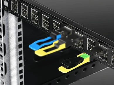
3. What Is an MTP Loopback Used For?
An MTP Loopback is useful in several stages of optical network deployment and maintenance. Its main purpose is to isolate and verify transceiver-related signal paths without requiring a complete remote connection.Testing Optical Transceiver Transmit and Receive Functions
One common application is checking whether an optical transceiver's TX and RX channels can operate together. By returning transmitted signals to the receiving channels, technicians can identify potential issues with the module or its optical interface. This test is useful during initial equipment installation, module replacement, and routine maintenance. It can also help determine whether a suspected fault is associated with the transceiver or another part of the network.Verifying Fiber Channel Connectivity
Multifiber transceivers rely on several optical channels operating in the correct arrangement. An MTP Loopback allows technicians to check the channel connections within a compatible interface. For example, an 8-fiber configuration may support four TX and four RX channels in an SR4 application. Testing the connections helps confirm that the required optical paths are established and that the channel mapping is correct.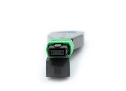
Troubleshooting Network Connection Issues
In case of a failed optical link connection, the reason might be a broken transceiver, a dirty connector, a broken fiber optic link, or incorrect polarization. To determine the reason for this problem, it is useful to conduct a loopback test. The steps of such a procedure should include:- Check the fiber-optic connector end face and clean it using an appropriate fiber-optic cleaning device.
- Verify that the transceiver, the connector type, fiber mode, and polarity match each other.
- Attach the loopback accessory and monitor the link or diagnostic status of the module.
- Carry out comparisons with the results obtained from a good transceiver or a testing setup.